A large challenge faced by the transportation sector is how to balance efficiency, sustainability, and comfort. The Hyperloop is planned to be a high-speed train with the goal of getting travelers from one place to another as fast and as sustainably as possible. The design is not yet complete and university clubs, such as the University of Toronto Hyperloop Team (UTHT), help to improve the design by competing in design competitions. For my capstone project, I worked with a multidisciplinary team of engineers to redesign the power system for the UTHT’s pod design. This required designing a custom power distribution system, intelligent HV / LV switching logic, cutting-edge communication system, custom battery architecture, 3D-printed battery encasings, and a Graphical User Interface. Extensive testing and safety evaluations were performed to demonstrate the functionality of the system and ensure that it was safe to use within a student-led design team. This design was demonstrated at the Capstone Showcase with a live demo of the system.
The code for the project can be found on GitHub here.
Background
The Engineering Capstone Project is a requirement to complete a Bachelor of Applied Science (BASc) at UofT. It is a yearlong project demonstrating rigorous research and design to meet the needs of a client. It is the culmination of the four years of study towards the BASc degree.
The University of Toronto Hyperloop Team (UTHT) is a design team at the University of Toronto that competes in yearly competitions to design a high-speed pod used to transport people and goods over long distances. The pod has complex power requirements, requiring at least 270V DC to power the propulsion system and 24V, 12V, and 5V DC to power the electronics on the pod. Since the power system will be operated and maintained by undergraduate university students, the main design objectives of the power system were safety, modularity, and ease of assembly.
Design
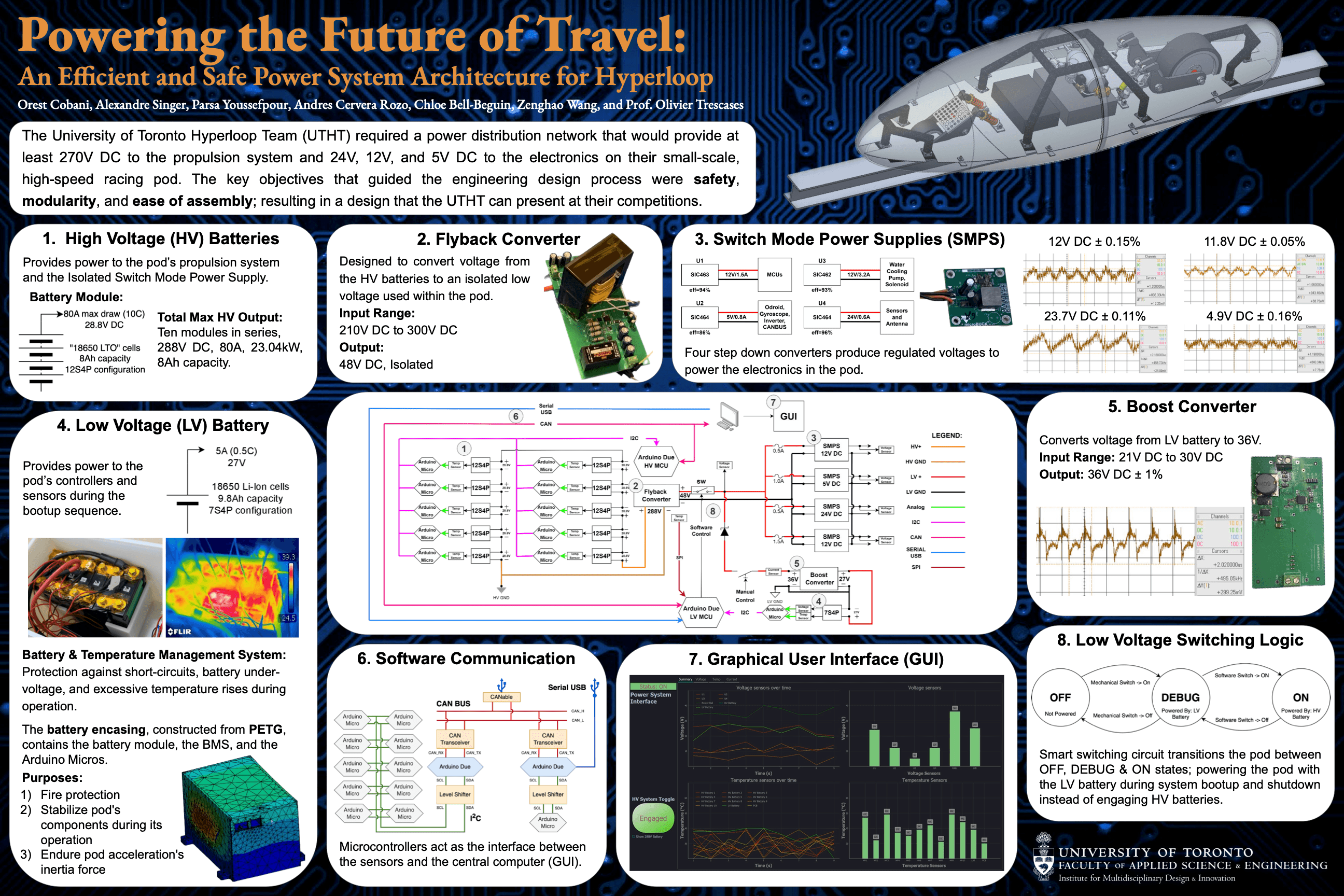
The design consists of 8 main sections: High Voltage (HV) Batteries, Flyback Converter, Switch Mode Power Supplies (SMPS), Low Voltage (LV) Battery, Boost Converter, Software Communication, Graphical User Interface (GUI), and Low Voltage Switching Logic.
These 8 sections, shown in the poster above, work together to meet the client’s needs.
1. High Voltage Batteries
The High Voltage Batteries are the main source of power within the pod. They are composed of 10 Battery Modules, with each Battery Module consisting of “18650 Lithium Titanate” cells in a 12S4P configuration. Each battery module can provide up to 80A (10C) at 28.8V DC with a capacity of 8Ah. These 10 Battery Modules are connected in series providing 288V DC.
The 288V DC are fed into an Inverter on the pod, to power the propulsion system, as well as the Flyback Converter, to provide power to the electronics of the pod during operation.
2. Flyback Converter
The Flyback Converter is a custom-made circuit designed to convert a 210V - 300V DC input voltage into a regulated 48V DC isolated output. The isolation was important since users of the design may be working with the electronics on the pod while the pod is powered, so isolating the HV batteries from the rest of the circuit provides a layer of protection from potential shocks.
The 48V DC is used to power a node in the circuit which acts as a voltage reservoir that feeds four Switch Mode Power Supplies.
3. Switch Mode Power Supplies (SMPS)
The Switch Mode Power Supplies are Buck Converter circuits which are designed to step down the voltage from the voltage reservoir and produce different regulated voltage rails.
There are four voltage rails produced by this design:
- A 24V rail which powers some sensors and antennas.
- A 12V rail which powers a water-cooling pump and a solenoid.
- A 12V rail which powers the microcontrollers on the pod.
- A 5V rail which powers the main computer on the pod (the Odroid), a gyroscope, the Inverter, and the CANBUS.
These rails were chosen to evenly distribute the load of the circuit, and each provide a regulated output within 0.15% tolerance.
4. Low Voltage (LV) Battery
As well as having HV Batteries, the power system contains LV Battery which provide power to the electronics on the pod during boot up.
The LV Battery consists of a single module of 18650 Li-Ion cells in a 7S4P configuration which have a capacity of 9.8Ah. The max draw of these batteries is expected to be 5A (0.5C) at 27V DC.
A Battery & Temperature Management System (BMS) is used to protect the LV battery against short-circuits, under-voltage, and excessive rise in temperature.
A custom, 3D-printed battery encasing was designed and constructed out of PETG. The battery encasing holds the battery module, the BMS, and the Arduino Micros (which monitor the temperature of the battery). The main purposes of the encasing is to protect the battery in the case of fire, stabilize the components of the pod during its operation, and endure the inertial forces produce by the pod’s acceleration.
The 27V DC produced by the battery are fed into a Boost Converter to raise it to a higher voltage.
5. Boost Converter
The Boost Converter is a circuit designed to take the 27V DC, produced by the LV Battery, and produces a 36V DC regulated output with a tolerance of 1%. Since the battery voltage will decrease as it discharges, the Boost Converter regulates the output of the battery to a constant voltage.
6. Software Communication
To monitor the state of the pod and control the different systems within, a Software Communication System was implemented.
Throughout the power system there are sensors that measure temperature, voltage, and current. These are used to ensure that the power system is operating within safe thresholds. Arduino Microcontrollers (MCUs) are used to monitor these sensors and relay the information to an on-board computer. During real operation the on-board computer would be an Odroid; however, for the demonstration and testing of the system by the Capstone team, a standard laptop computer was used to read the signals and display it on a GUI.
Within each Battery Module (both LV and HV) is an Arduino Micro MCU which monitors the temperature of the module. This information is relayed to an Arduino Due over I2C. Since Arduino Micros and Arduino Dues have different operating voltages, level shifters were used to allow for communication between the different MCUs.
There are two Arduino Dues within the system: a HV MCU, which monitors the HV system; and a LV MCU, which monitors the LV system. They each respond to their respective Battery Modules as well as monitor other sensors within their domain. The Arduino Dues communicate their sensor values to the on-board computer over a CANBUS, a standard communication protocol used in the Electric Car industry. To facilitate this communication, SN65HVD230 CAN Transceivers were used. The CAN protocol was chosen for this application as, being an industry standard, it had a lot of support, and it allows for messages to be sent at different priorities. This allowed for safe communication within the pod.
For the demonstration of this Capstone project, the laptop computer connects to the CANBUS through a CANable USB to CAN interface.
As well as reading sensor data throughout the power system, different signals needed to be sent into the system: A LV Switch signal, which signals the pod to go from the “Debug” state to the “On” state; and Buck Enable signals, which enable the different SMPSs in the design. These signals are handled by the LV MCU, which are activated by commands sent from the on-board computer via a Serial-USB interface.
For the demonstration of this Capstone project, the sensor data and signals are controlled by a Graphical User Interface (GUI).
7. Graphical User Interface (GUI)
The GUI displays the sensor data throughout the pod in a user-friendly way; allowing the user to easily deduce the health of the power system and make decisions on how the power system is running. It includes line and bar graphs which display the temperatures, voltages, and currents throughout the pod. It includes tabs that allow the user to see specific sensors that they may be interested in.
The GUI contains safety logic that automatically shuts off the power system if it detects sensor values above or below preset thresholds.
The GUI also contains a button that allows sends a command to the LV MCU, telling it to turn the pod on, directing power from the LV Battery to the HV Batteries through the Low Voltage Switching Logic.
8. Low Voltage Switching Logic
The Low Voltage Switching Logic decides where the power for the electronics on the pod will be provided by.
When the pod first starts up, it is important that power is not coming from the HV Batteries. The idea is that, during startup, only certain things are powered (such as the MCU and communication system) which allow the user to debug the system and ensure that everything is working well before powering the system off the HV Batteries. A Schottky diode, BJT transistor, and mechanical switch are used to facilitate this transition.
The user would first turn on the pod by physically turning on the mechanical switch which will put the pod in “Debug” mode. At this time the transistor would be off, and the diode would be in forward bias, meaning that power is coming from the LV Battery through the Boost Converter. During this time, only the SMPSs used for debugging would be enabled and the MCU would send sensor data to the on-board computer.
If the sensor values are within acceptable range, the user can remotely turn the pod from the “Debug” mode to the “On” mode by turning on the transistor. This would keep the user physically distant from the power system while the pod is on. When the transistor is turned on, the Flyback Converter would be providing 48V DC to the central node. Since the Boost Converter produces 36V DC, the diode would be in reverse bias; meaning that the power of the electronics would be provided by the HV Batteries.
The user can then disengage the HV Batteries using the GUI, returning the pod to “Debug” mode, before safely being able to shut off the power system using the mechanical switch.
Testing
The system was tested to ensure that the power system was operating as expected. This included tests on the batteries including their internal resistances; the BMS, to ensure that it could detect under voltage; the temperature sensors under load; the CAN communication system; the continuity after installation; and the GUI validation.
These tests all showed that our design worked and met our client’s needs.
Demonstration
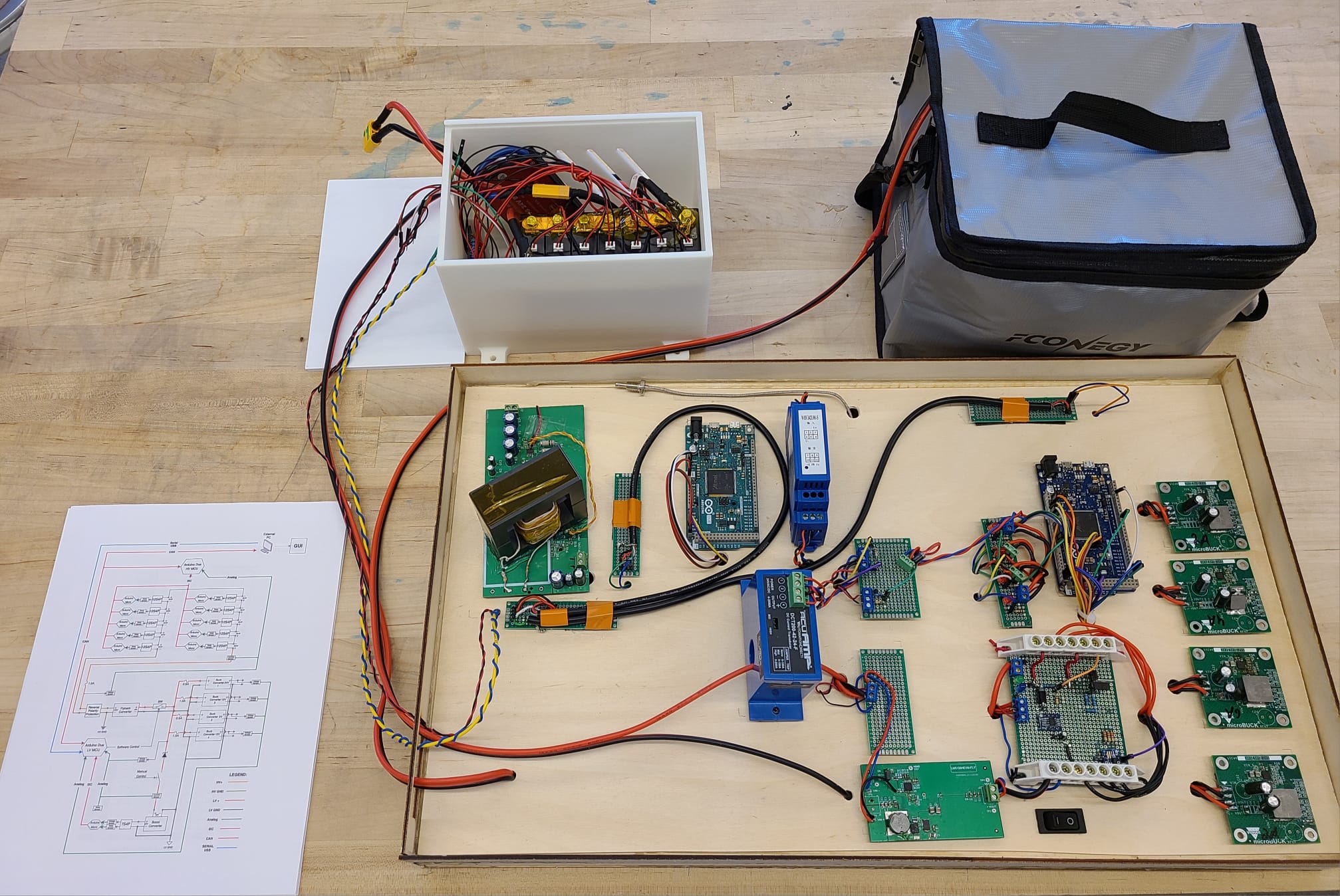
The design was demonstrated to our supervisor and other clients at the 2023 APS490 Capstone Showcase. A working demo was demonstrated showing off the GUI (including the Software Communication), the power conversion of the SMPSs, and the Low Voltage Switching Logic.
A One-Pager was also provided to the people at the showcase to introduce them to our design.
A handout was also provided to viewers to help communicate important aspects of the project we could not demonstrate at the showcase.